

By Venny Yang, president, and Sam Hsieh, senior deputy technical manager
CoreTech System (Moldex3D)
In 2016, ANSYS became the first engineering simulation software company to achieve annual revenue of more than $1 billion. This revenue scale not only surpasses most CAD/CAM software companies, but also officially declares the era of CAE-driven design has arrived. In February 2017, Hexagon AB, the world-leading company of precision measuring machines, acquired MSC Software, one of the most experienced companies in the CAE software industry, for $834 million. This acquisition represents a big step for hardware companies entering the digitalized design, and it indicates the measurement of data in real manufacturing environments will be closely integrated with simulation analysis. This will help break the limits in part design optimization and traditional production while leading the manufacturing industry on the journey to Industry 4.0.
These transitions and integrations will continuously drive creation and innovation in global electromechanical and related industries. The same design optimization and evolution of simulation technology also will take place in the world of injection molding and mold design.
Role transition of mold-filling analysts
In the beginning, mold-filling simulation was only applied to the diagnosis of plastic part design to solve production problems. Currently, it has evolved into a tool that is massively used on early design, verification and optimization of part and mold development. It plays an essential role in the design and manufacturing processes in most enterprises. The widespread application of full-3D CAD software for part and mold design contributes significantly to this transition, but automatic mesh generator capability assists, too. In the early days, analysts spent hours on modeling and meshing before analyzing. Now, the mesh can be updated synchronously with part modification. Therefore, the task of standard mold filling analysis has gradually shifted from the professional CAE analyst to the mold designer or even to the product designer.
Product and mold designers are used to relying on analysis software to determine the position of sprue, balance the runner design, optimize the cooling channel deployment, solve warpage, etc. Moreover, many companies have started to embed the core of mold filling analysis in their internal design guide platforms to realize the design quality management ideal in which every part is processed by mold filling analysis to automatically inspect the upper limit of injection pressure, shrinkage and warpage
An automatic runner mesh generator helps users save considerable time by generating the appropriate 3D runner mesh for mold filling analysis. Runner mesh technology can automatically create hexahedral mesh with high resolution, provide users with various node types to connect line runner junctions, reflect the original geometric shape of runners, and further save computing time while improving simulation accuracy.
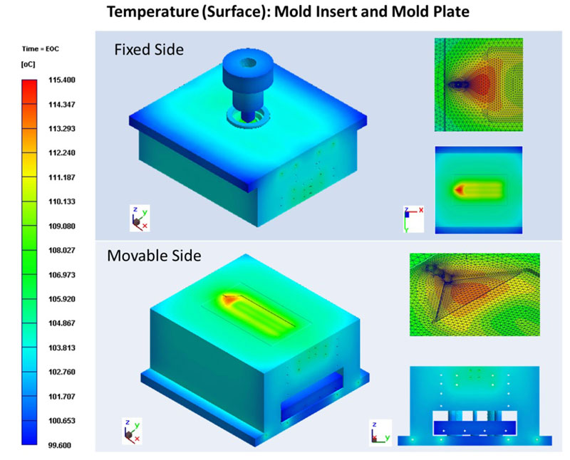
With the emergence of “non-matching mesh” technology, users can go straight to the simulation analysis to get accurate simulation results and deformation prediction of interconnected parts, even when the mesh interface between the part and the part inserts does not continuously match the quantity. The non-matching mesh technology, which used to support the part inserts and mold base, now is extended to support the mesh of mold inserts/plates, so the complete injection mold can be fully supported by non-matching mesh technology. This surmounts the restriction that a 3D solid mold base mesh cannot be pre-processed automatically when mesh nodes of the part and the part inserts are not matching (Figure 1).
Expansion to special processes
In addition to the simulation analysis of standard injection molding processes, the mold analysis function also covers special processes – for example, injection compression molding, compression molding and metal injection molding. Fiber orientation and FEA-integrated analysis of short and long fiber reinforced plastics (FRP) during the injection molding process are featured. These benefits also extend to the compression molding process analysis of FRP to assist users in designing and optimizing the manufacturing process of large-scale FRP. Moreover, the enhanced and patented simulation approach, which adds Herschel-Bulkley yield stress to the Cross-WLF viscosity model, ensures more reliable fiber orientation results in the core region with improved prediction accuracy.
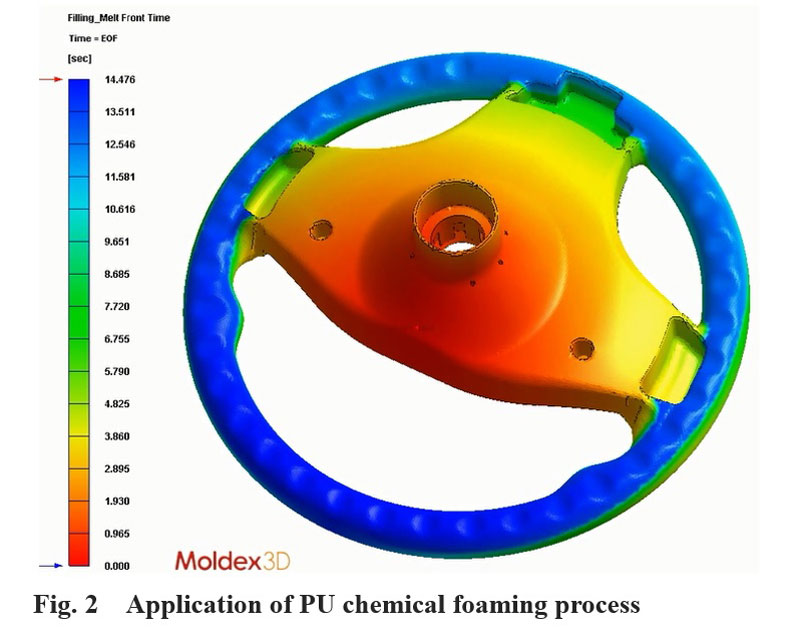
In addition to the full support of FRP processes, as the requirements of lightweight and fuel-efficient vehicles keep increasing, software has integrated advanced molding technologies, such as gas-assisted injection molding, water-assisted injection molding, microcellular foam injection molding (typical technology: MuCell® by Trexel) and chemical foaming of thermoplastics into the scope of simulation prediction. Chemical foaming analysis also supports polyurethane (PU) foaming and considers the curing kinetics when the glue is in the die cavity as well as the computing of foaming kinetics. Through PU foaming simulation analysis, users can accurately predict the dynamic behaviors during filling and foaming stages, identify the optimized control of injection conditions and material injection, refine the part design, and evaluate and determine the ideal manufacturing conditions (Figure 2).
In-mold decorating
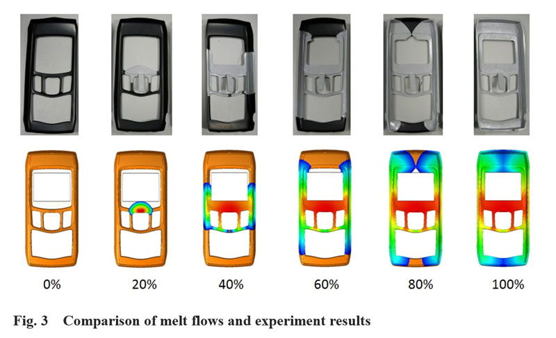
Though in-mold decoration (IMD) injection molding has become popular in recent years, it still faces challenges from molding processes such as ink wash-off and wrinkle deformation, which result in a higher cost and delay of product development schedule. Analysis functions support boundary options of thin films in IMD simulation and help users process the mesh layer of decorative pieces with the fastest, simplest and most accurate approach. Furthermore, it also provides a “wash-out index” to enable designers to predict washout status and ensure the output of high-quality in-mold decorative products.
With the analysis, users can predict the flow front identical to actual results and gain insight to the heat hesitation during the molding process by considering the heat transfer effect of thin films. This phenomenon is caused by a weaker heat transfer ability of the decoration layer (Figure 3).
3D printing changes the landscape
3D printing is another new technology that has started to change mold design. The price of a 3D metal printer is becoming lower, and the cost of metal powder is decreasing yearly. The printing of small- and medium-sized molds is not a dream anymore, and the heat power accumulation that often occurs around the ribs and holes of medium- to large-sized molds can be eliminated by integrating traditional mold manufacturing processes and 3D printing.
Besides remarkably decreasing the types and numbers of required processing equipment, the biggest benefit is the flexible cooling channel design. 3D conformal cooling can easily cool all corners of the mold; it can significantly save cooling time and decrease the warpage and sink mark on the product surface. In the design stage, 3D CFD can be used to check if the turbulent flow in every channel is sufficient to ensure cooling efficiency and evaluate the required pressure and specification of the cooling pump. The traditional and conformal cooling channels in the mold are then evaluated by the combination of cooling and warpage analyses to assess the manufacturing cost of the mold, cooling time reduction under mass production and the manufacturing cost with enhanced stable quality and efficiency. As stated previously, the widespread utilization of 3D printing technology is rapidly changing the landscape of mold manufacturing and leading the popularization of conformal cooling channels.
Embrace Industry 4.0
The emerging trend of cloud computing substantially drives the development of e-commerce and AI, gradually making it an important option when CAE software suppliers and users consider the investment and deployment of next-generation computational resources. As the confidentiality of design information stored in public clouds still is questionable, many enterprises have introduced cluster computing architecture internally to correspond to the requirements of macro memory and computing time of CAE computing. For example, well-known CAE software, such as ANSYS and ABAQUS, has already provided support to cluster computing. As intellectual property protection, network security and transmission bandwidth are getting more mature, enterprises start to consider the benefits brought by cloud computing.
When more manufacturers are using mold filling analysis to improve business competitiveness in design, manufacturing and production processes, it means more computing data will be generated. These data, through integration with various data measured on site, form the essential base for enterprises on the journey to Industry 4.0.